
Reversed foil side view
Altimeter
(Maximum Recording Model Rocket Altimeter
For small rockets and aircraft
update: 7/15/06
The following
circuit was designed to provide an inexpensive, simple and easy to construct
altitude recorder for small model and amateur rockets.
Every effort was made to keep the design simple and within the
capabilities of most amateur experimenters as well as to provide accurate and
useful functionality. The circuit
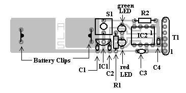
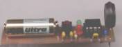
is small measuring 2 5/8 inches by 9/16 inches and weighs only about 0.3 ounces.
It features PCB construction using standard size through-the-hole
components. Also, it is cheap
enough to be used in “risky” launches and durable enough to survive the
occasional mishap.
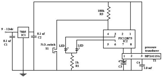
Theory of operation:
The circuit is
designed around a PIC 12F675 flash microcontroller (IC2).
Pin 7 of IC2 performs an analog to digital conversion (A/D) of the
voltage produced by T1 an absolute pressure transducer.
The transducer used has a high level output (0.2 to 4.8 volt), which
interfaces directly to the microcontroller.
Pins 3 and 6 are used to output the altitude and operational data to LEDs.
Switch S1 is used to trigger the output of the maximum-recorded altitude
since “power-on”. Power is
provided by a 23A “lighter” battery and IC1, a linear voltage regulator.
The microcontroller
program is written in Microchip assembler using their MPLAB-IDE development
software and programmed on a microchip Flash Starter Kit.
The program is composed of a series of subroutines, which should make the
program easy to modify if the builder so desires.
A free copy of the program can be downloaded from jbgizmo.com or a
preprogrammed microcontroller can be purchased from the same source.
The output of the
circuit is in A/D units (0-1024) and must be converted to an altitude
measurement mathematically. This
mathematical calculation is described in detail in the operational portion of
this document. An Excel
spreadsheet chart is available for download from jbgizmo.com, which makes
computing the altitude easy and it is more suitable for field use.
The Pressure
transducer output equation:
Vout=Vs(0.009P-0.095)+-
error
P=pressure in kPa
Vs=5 volt
Temp= 0-85 C
The altitude
calculation:
ph= [(A/D reading x 0.032047 + 3.11754]
Altitude in feet
={[10log(ph/p)/5.2558797]-1}/
(-6.8755856 x 10⁻⁶)
p= sea level pressure (obtained from the local weather station or NOAA weather
broadcast)
ph= station pressure measured and read from the circuit. These A/D units will
need to be converted to inHg using this formula… station pressure
inHg= [(A/D units * .032047)+3.11754]
Construction is straightforward. Etch
and drill a circuit board according to the pattern provided and solder the parts
on the circuit board as indicated in the drawing.
The only tricky procedure is the construction of the battery holder.
The battery holder
is composed of the spring ends of two #1 safety pins. Cut and remove the clasp end of the safety pin, extend the
ends through the PCB, fold ¼ inch over and solder flat against the foil.
This makes a nice small battery holder but may be a little awkward to
construct. If the builder would
like, any “N” size battery holder can be used instead.
|
|
|
|
|
|
|
|
|
Parts:
|
Resistors |
Description |
part
number |
Supplier |
|
R1 |
1000
ohm 1/4w |
291-1K |
Mouser |
|
R2 |
100k
ohm 1/4w |
291-100K |
Mouser |
|
Capacitors |
|
|
|
|
C1,
C2 |
0.1uf |
|
Mouser |
|
C3 |
470pf |
|
Mouser |
|
C4 |
1
uf |
80-T350A105K025 |
Mouser |
|
Semiconductors |
|
|
|
|
IC1 |
78L05
(5volt regulator) |
LM78L05ACZNS-ND |
Mouser |
|
IC2 |
PIC12F675 (micro
controller) 8 pin DIP |
579-PIC12F675-I/P |
Mouser |
| for a pre-programmed IC2 click here | |||
|
LED1 |
LED
red |
604-L934ID |
Mouser |
|
LED2 |
LED
green |
604-L934GN |
Mouser |
|
Sensor |
|
|
|
|
T1 |
Absolute
pressure sensor |
MPX4115A-ND |
DigiKey |
|
Other |
|
|
|
|
Switch |
Tactile
switch, SPST Momentary, NO |
688-SKHVBA |
Mouser |
|
IC
socket |
8
pin DIP socket |
649-DIP-306-001B |
Mouser |
|
B1 |
12 volt small
“lighter” type |
573-23A |
Mouser |
|
Battery
clips/holder |
Spring
ends of #1 safety pins |
|
|
|
PCB |
See
foil pattern above |
|
|
|
plastic
shim |
Used
as on/off switch |
Insert
between battery and battery clip |
|
|
Firmware |
|
|
|
|
PIC
program listing |
|
Download
jbgizmo.com |
|
|
Software |
|
|
|
|
Excel
formatted chart |
|
Download
jbgizmo.com |
Operation:
Example Chart Reading
(download the complete chart from jbgizmo.com)
Example#1 if you
know the launch site altitude: If your launch site was at 1,800 feet and your
Altimeter read 803 when you first turned it "on" you would read down
the left column to find the A to D reading of 803 then read across to find the
altitude closes to you launch site altitude, which would be in column
"3" (1,798). If after your rocket's flight the altimeter was
reading 797 then you would read down the left column to 797 then across to
column 3 and read "1,980". 1,980 feet above sea level is the
highest altitude that your rocket reached. Subtract the launch site altitude
(1,798) from the maximum altitude (1,980) and you have the vertical altitude
flown by your rocket (182 feet).
Example#2 if you
know the sea level pressure: If your sea level pressure is 30.91 inHg, find
the column that has the pressure closes to 30.91 inHg. You will find the
closes value to 30.91 inHg in column "2". Read down the left
column to find the preflight A/D pressure reading, then read across to column
"2" to find the preflight altitude. Repeat the process for the
post flight reading in order to find the maximum altitude achieved.
Example section of chart
|
|
1 |
Cal factor |
|
1 |
2 |
3 |
|
altimeter reading |
|
|
sea Level kPa |
104.97 |
104.63 |
104.29 |
|
A to D |
inHg |
kPa |
sea level inHg |
31.00 |
30.90 |
30.80 |
|
803 |
28.851 |
97.69 |
|
2005 |
1886 |
1798 |
|
802 |
28.819 |
97.58 |
|
2035 |
1917 |
1828 |
|
801 |
28.787 |
97.47 |
|
2065 |
1947 |
1858 |
|
800 |
28.755 |
97.36 |
|
2096 |
1977 |
1889 |
|
799 |
28.723 |
97.26 |
|
2126 |
2008 |
1919 |
|
798 |
28.691 |
97.15 |
|
2157 |
2038 |
1950 |
|
797 |
28.659 |
97.04 |
|
2218 |
2069 |
1980 |
|
796 |
28.627 |
96.93 |
|
2248 |
2099 |
2011 |
Note: that a calibration factor is included at the top of the chart. This value can be used to fine-tune your altimeter readings. In most cases a “Cal factor” will be between 0 and 1.
return to home page
Copyright ©,Jerry Baumeister
Revised 10/3/04